 Dedicated to the late WIB Pitman of Newport IW, a true gentleman. He could have told us so
much more.
Dedicated to the late WIB Pitman of Newport IW, a true gentleman. He could have told us so
much more.- The Chain Home (CH) RDF System-
Dedicated to the late WIB Pitman of Newport IW, a true gentleman. He could have told us so
much more.
Many accounts of the beginning of Radio Direction Finding radar suggest that it was 'invented' by Watson-Watt in the UK. However there had been earlier demonstrations in America of radio detection
of aeroplanes, and Herr Christian Hulsmeyer's idea for an anti-collision-of-ships device was patented as far back as 1904 and this led to German radar being developed in time
for the war. Indeed, by then both the Americans and the Japanese also had some form of RDF too. In England Marconi had discovered in the nineteen twenties that short-wave wireless signals were
reflected from solid objects. In addition the Post Office had received numerous complaints of short wave wireless reception being affected by passing aircraft and the Post Office found that in 1933 at
Daventry their own experimental 'wireless' telephone was interfered with in the same way.
The construction of these top-secret RDF installations must have greatly intrigued the local populace and it is reported that there was much speculation regarding the possibility of 'death rays'.
To understand how the system worked, from the outset it should be realised that the CH system bore no resemblance to the well known rotating radar of today. Fixed vertical aerials suspended
between the platforms on a tall steel tower radiated extremely powerful pulses of radio waves and a nearby similar aerial mounted on a shorter wooden tower (a steel tower would have inhibited
the received signals), received the tiny signals (echoes) re-radiated from the metallic target. It should be noted that the transmitting aerials to some extent wastefully radiated over the full 360 degrees around them
and initially the RDF receiver aerials could pick up unwanted signals from the opposite direction to the intended line of shoot i.e the centre bearing of the radiated approximate 60 degree arc. Additional operator
selectable receiver aerial elements were added in 1940 to cancel this backward reception. Because a choice of four spot frequencies were specified to enable a countermeasure for anticipated enemy
'jamming', four transmitting and four receiving aerials of different lengths were needed. That is why there were four transmitter towers and four receiver towers. Looking back over the 65 years, one is struck by the quite remarkable specification of CH, given the short development period. The transmitter designed by the brilliant Dr.Dodds of Metrovick
used his earlier invented commercially secret state-of the-art water cooled and continuously evacuated valves which provided a unique output power for those times of about 300 kilowatts (which
was later doubled when 50 Hz full wave modulation was changed to true pulse modulation) on a choice of four predetermined frequencies between 20 & 60 MHz. The pulse length could be switched
to 5 or 40 microseconds and the pulse repetition frequency (PRF) was a low 25.
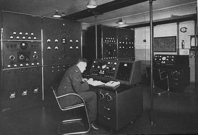
Inside T Block showing the duplicated equipment
The theoretical range was about 200 miles and a reliable 150 was eventually achieved when pulse modulation was adopted, with a claimed accuracy of 1 mile at 15000 feet. In addition, by
transmitting different lobes of RF energy from aerials mounted at different points up the towers, the target height could be determined by comparison of the amplitude of the returns, to an accuracy
of 500 feet. The enemy quickly became interested in these 350 foot towers and before the war started sent the Graf Zeppelin airship three times along our
east coast to monitor the emissions. However certain aspects of our system caused the German investigators to become baffled. Their expectations were based on the working of their own radar
systems so they were looking for much higher pulse repetition rates transmitted on much higher frequencies. Also their own Freya long range radar rotated continuously, so they expected any
detected radar signal to come and go rhythmically. Finally the mass of the metal framework within their airship probably prevented any directional aerial system they had from working properly.
All they detected was a fifty hertz buzz and fortuitously for us, they assumed wrongly that they were picking up radiation from defects (sparking) in our 50Hz alternating domestic mains electricity
system, this conclusion aided no doubt by the fact that all our CH stations transmitted in synchronism by using a timing pulse derived from the mains waveform to achieve that. All four of the wooden receiver towers were completed in 1938. During construction of No.1 steel tower in July 1939 by Messrs. J. L. Eves &Co, John Painter a 22 years old erector fell about eighty
feet down the centre of the pylon to his death. A week later Frank Shatterly aged 40, lost most of his third finger of his left hand when working at the very top of the tower, but managed to climb down
safely. RAF Ventnor became operational in an 'intermediate' form at the end of January 1939. As the steel towers were not completed, initially two of the wooden 240 foot ones were used to support one
transmitting and one receiving aerial. Both T & R blocks were built of 18 inch brickwork and protected all round to roof height by concrete and earth embankments, but the equipment in them was not
yet up & running. Even so, the station had to be put on a war footing on the 24th August and at that 'intermediate stage' the hardware was housed in wooden huts and the photo below is of Ventnor's
somewhat overcrowded R hut.  Watson Watt set up his base for experiments
first at Orfordness then at Bawdsey in Essex. His staff, some of whom were volunteers there at the weekends only, at first worked with the 50 metre wavelength and achieved a range of 80 miles but
it was concluded that 10-15 metres would give better results as that was closer to the wingspan of the expected target aircraft. In addition it was found that a much more powerful transmitter would be
required together with higher aerials.
Watson Watt set up his base for experiments
first at Orfordness then at Bawdsey in Essex. His staff, some of whom were volunteers there at the weekends only, at first worked with the 50 metre wavelength and achieved a range of 80 miles but
it was concluded that 10-15 metres would give better results as that was closer to the wingspan of the expected target aircraft. In addition it was found that a much more powerful transmitter would be
required together with higher aerials.  Bawdsey Manor on the remote Suffolk coast continued to be
used by Watson Watt as his R&D centre and working with A.P.Rowe (who had been unsuccessful in his own experiments to achieve infra-red detection) they together created in 1937 the first operational
Radio Direction Finding Chain Home (CH) system for use by the RAF. The following year Bawdsey developed its control system by directing fighters from Biggin Hill to commercial airliners flying over
the sea. During this time it was found that CH was deficient in detecting aircraft at low altitudes and an entirely separate system (CHL) was quickly designed to do that. Bawdsey, which commenced as
a 'think tank' employing "brainstorming" sessions known as "Soviets" was initially run in a relaxed manner more like a gentlemens' club within a seaside holiday hotel. It evolved into the premier radar
development, training and support establishment in the pre-war years, although the scientists neccessarily had to move away when war was declared, first and briefly to Dundee, then to Worth
Matravers in Dorset before finally moving on to Malvern. A first hand account of their activity in these fraught years, written by one of those scientists, Dr.W.H.Penley may be found at
Penley Archives. Oral history may be heard at
Radar Recollections.The transmitters and receivers which they eventually evolved were then
manufactured by civilian companies sworn to secrecy. The towers were constructed by civilian contractors, but the aerials they supported were commissioned by RAF
specialist teams based at West Drayton. The whole enterprise was supervised to some degree by the Bawdsey boffins. The east coast chain was constructed during 1938/39, Ventnor being the last.
Mr.Chamberlain would have known that the Bawdsey people were successfully tracking commercial flights and that the completion of a working system of defence was imminent and his (now usually derided)
negotiations with Hitler in September 1938 bought time for this and for the building of many squadrons of Spitfires.
Bawdsey Manor on the remote Suffolk coast continued to be
used by Watson Watt as his R&D centre and working with A.P.Rowe (who had been unsuccessful in his own experiments to achieve infra-red detection) they together created in 1937 the first operational
Radio Direction Finding Chain Home (CH) system for use by the RAF. The following year Bawdsey developed its control system by directing fighters from Biggin Hill to commercial airliners flying over
the sea. During this time it was found that CH was deficient in detecting aircraft at low altitudes and an entirely separate system (CHL) was quickly designed to do that. Bawdsey, which commenced as
a 'think tank' employing "brainstorming" sessions known as "Soviets" was initially run in a relaxed manner more like a gentlemens' club within a seaside holiday hotel. It evolved into the premier radar
development, training and support establishment in the pre-war years, although the scientists neccessarily had to move away when war was declared, first and briefly to Dundee, then to Worth
Matravers in Dorset before finally moving on to Malvern. A first hand account of their activity in these fraught years, written by one of those scientists, Dr.W.H.Penley may be found at
Penley Archives. Oral history may be heard at
Radar Recollections.The transmitters and receivers which they eventually evolved were then
manufactured by civilian companies sworn to secrecy. The towers were constructed by civilian contractors, but the aerials they supported were commissioned by RAF
specialist teams based at West Drayton. The whole enterprise was supervised to some degree by the Bawdsey boffins. The east coast chain was constructed during 1938/39, Ventnor being the last.
Mr.Chamberlain would have known that the Bawdsey people were successfully tracking commercial flights and that the completion of a working system of defence was imminent and his (now usually derided)
negotiations with Hitler in September 1938 bought time for this and for the building of many squadrons of Spitfires. 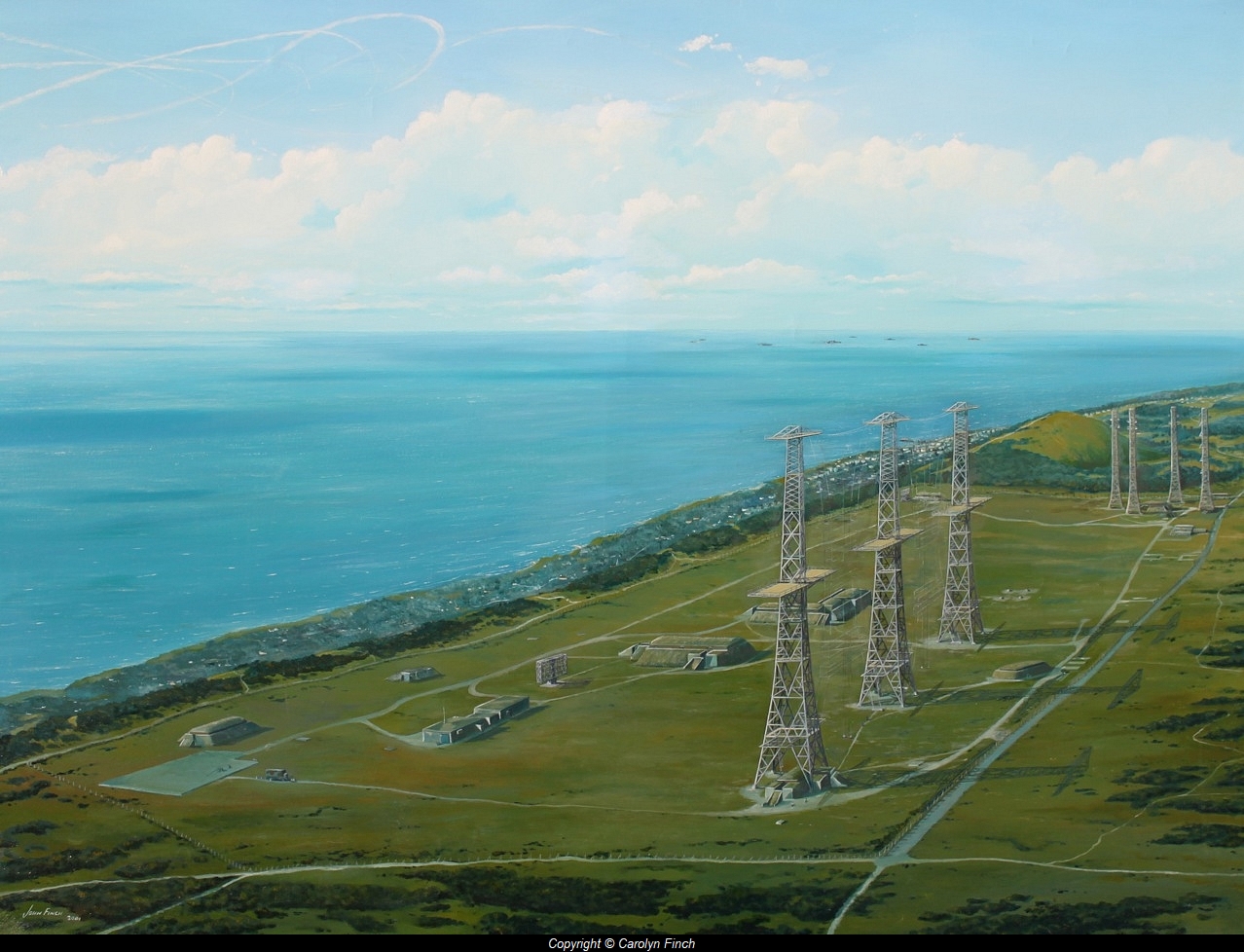
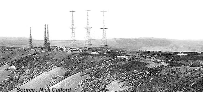
The wooden receiving aerial towers with four transmitter towers in line to the rear
So how could this non-rotating equipment produce the required result? The very technically sophisticated and sensitive Cossor built receiving apparatus culminated in a 12 inch cathode ray
tube (CRT) which showed a horizontal bright line (the trace) and a fixed scale calibrated in tens of miles above it. This trace in fact looked like a waving line of short grass as the 'background noise'
caused small vertical deflections in it. 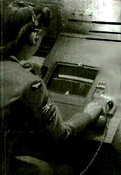 The trace originated from the left side of the CRT and was re-initiated by each transmitter pulse, successive pulses causing the trace to be repeatedly redrawn towards the right. Any echo received
in the time between transmitter pulses, provided it was of a strength greater than that of the 'grass', caused a vertical downwards deflection of the trace, appearing usually as a narrow spike and
thus the range could easily be read off against the scale. However the variation of shape and amplitude of such 'spikes' gave an experienced operator some indication of the number of aircraft in
an approaching formation. The exact bearing was not so immediately obvious, but at Ventnor was always going to be within 30 degrees of either side of 148 degrees (about SSE), the designed
'line-of-shoot'.
The trace originated from the left side of the CRT and was re-initiated by each transmitter pulse, successive pulses causing the trace to be repeatedly redrawn towards the right. Any echo received
in the time between transmitter pulses, provided it was of a strength greater than that of the 'grass', caused a vertical downwards deflection of the trace, appearing usually as a narrow spike and
thus the range could easily be read off against the scale. However the variation of shape and amplitude of such 'spikes' gave an experienced operator some indication of the number of aircraft in
an approaching formation. The exact bearing was not so immediately obvious, but at Ventnor was always going to be within 30 degrees of either side of 148 degrees (about SSE), the designed
'line-of-shoot'.
However, there were two separated receiver aerials, one either side of the tower and the signals from each were fed to the famous 'goniometer'. This already existing device was a hand control
containing two coils, each provided with one of the aerial signal inputs. A third output coil fed the signal on to the display by means of the electromagnetic coupling between all the coils. By rotating
the knob one input coil moved mechanically in relation to the other.
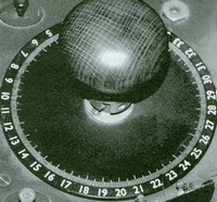 The effect achieved by sweeping the goniometer back and forth was exactly the same as if the receiving aerials themselves had swept across the sector centred on the line-of shoot. At one particular
point of the knob's rotation, the interaction of the two input signals caused a 'null' point where the displayed echo reduced significantly in amplitude. A scale in degrees arranged in a ring around the
knob allowed the bearing of the null-point to be read off, and this system refined the accuracy in determining the target's direction to within plus or minus 5 degrees. As the target progressed, only
tiny corrective rocking movements of the goniometer were needed to maintain the null point, and this gradually incremented around the scale of degrees until it disappeared completely from the
CRT display as the aircraft passed out of the fan shaped area over which the aerials could "see".
The effect achieved by sweeping the goniometer back and forth was exactly the same as if the receiving aerials themselves had swept across the sector centred on the line-of shoot. At one particular
point of the knob's rotation, the interaction of the two input signals caused a 'null' point where the displayed echo reduced significantly in amplitude. A scale in degrees arranged in a ring around the
knob allowed the bearing of the null-point to be read off, and this system refined the accuracy in determining the target's direction to within plus or minus 5 degrees. As the target progressed, only
tiny corrective rocking movements of the goniometer were needed to maintain the null point, and this gradually incremented around the scale of degrees until it disappeared completely from the
CRT display as the aircraft passed out of the fan shaped area over which the aerials could "see".
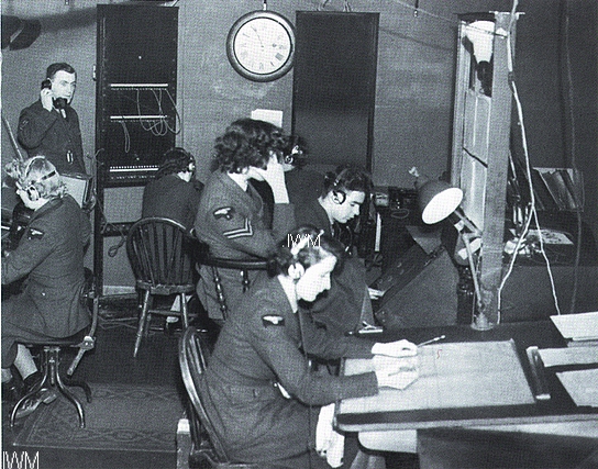
Interior of R Block showing one of the two display consoles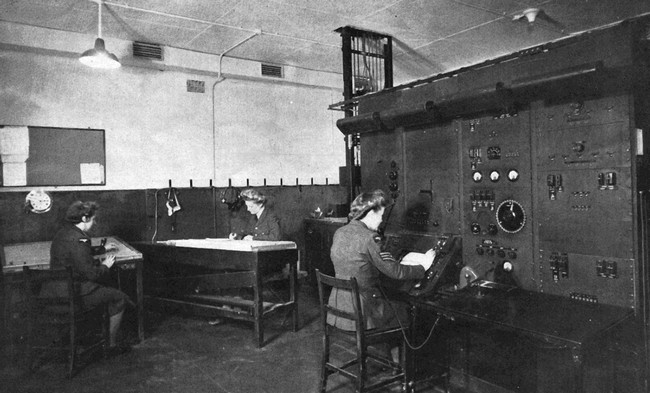
Next, a correction factor had to be applied and this was determined by reference to tables which had been drawn up when the 'calibration' of the equipment had been
done during the commissioning of the station. This was necessary because local geographical features distorted the shape of the transmitted lobes of radio frequency energy, in effect squinting
them to left or right, and the degree of squint varied at different heights. Calibration was achieved by an aeroplane (usually a dipole equipped Cierva autogiro
) flying in very tight circles over eight different points spread across the line of shoot and at various heights whilst remaining in sight through a theodolite mounted on the top platform of a
transmitter tower, while each visual and simultaneous RDF plot was made. Only the yet to be developed helicopter could have served the purpose better. In this manner co-ordinated tables of
the whole series of visual and RDF plots were compiled. Afterwards the radar co-ordinates were compared with the true visual plots and and correction tables duly created. The correction figures
obtained were projected out to cover the full extent of the range, and for all heights. Contrary to what might be read on other sites, the unarmed Cievra was not used to test the extent of the
range of CH, which for the south coast radars would have been fifty to a hundred miles into occupied France! Any change of frequency or aerial system required a new calibration run and because
of this calibration was behind schedule across the whole CH chain.
In use a target's bearing and range had to be corrected by reference to the tables and then applied to a map to obtain a grid reference for it. At busy times the system could be slowed down by this and as it had been anticipated an "optical converter" was devised to avoid the delay. Although It sounds unbelievable this worked by means of spring loaded strings around the gonio shaft and the range knob causing a mirror to be deflected thus thus diverting a spot of light over a grid map. However this device was never issued to the sites and indeed was made redundant by the introduction in 1940 of the "Calculator" which is described later. But what about the target's height? Well, the same goniometer was used, but this time switched to connect to aerials mounted on the towers at different heights and again a correction factor derived from the tables was necessary. However CH could not see aircraft flying much below 5000 feet nor those much above 20000 feet. Indeed, at Ventnor no heights at all could be established as the ground sloped away too steeply on the south east side and this lack of reflective medium prevented the formation of the neccessary lobes of electromagnetic energy. Wilkinson, who selected the sites knew this from the outset but chose the site in the knowledge that the coming Chain Home Low ought to work very well from it, as was later proved to be the case.
The next step in this process was to report the target's grid reference and height by voice via dedicated land-lines to a 'filter room'. There were seven of these
spread throughout the country and unusually Ventnor had to report to two of them, Stanmore in Middlesex and to Box near Bath. This was because Ventnor was located at the end of the Eastern
and the start of the Western chains. Friendly aircraft were identified by an entirely
separate system of HF direction finding which tracked the voice transmissions from the aircraft and these were also marked on the plotting table. The IFF system which made the echo from a friendly
aircraft brighter and larger could not always be relied upon, especially as in the early days not every aircraft was so equipped and sometimes those in the aircraft were loath to use it, fearing that the
enemy might make use of their signal. With the separate raids thus identified, the information was passed to an Operations room staff who could then make the tactical decisions regarding the
deployment and vectoring of the defending aircraft, either those already in the air or presently on the ground, towards their ever moving targets. It was found that those best equipped to calculate the
required courses were recuperating experienced pilots as they were able to visulise better the everchanging relationships between defending and attacking aircraft. However, once the enemy aircraft
had crossed the coast the CH RDF could no longer detect them and then the Royal Observer Corps reports to the
Filter Room became the sole means of tracking the enemy.
The Filter Room was the lynch pin of each area's RDF system as it received
information from all the several RDF stations in its area. The Filter Room staff determined which targets were friend and foe, and eliminated any obvious "mis-reports". Repeated plots became the
direction of travel (vector) with the height and estimated number of aircraft repeatedly confirmed. By cross referring reports from several different 'lines of shoot' further confirmation was provided.
As the Ventnor station looked to the south east, cutting across the lines of shoot of all the other south coast stations, its reports must have been of particular value in the cross referencing process.
Very quick thinking inside cool heads was needed to correctly assess the constant streams of ever changing reports. The edited data was assembled as markers on a large plotting table and this
showed the situation as it had been something like four minutes previously : since then the bombers would have flown on about another fifteen miles. 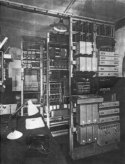 The system of having to use correction charts before reporting plots to the Filter Room as map grid co-ordinates contributed to the four minute delay and and sometimes of course the human factor
introduced errors in doing this. This problem was solved by Type Q, otherwise known as 'The Calculator' and the "Fruit Machine". Designed in 1939 by G.A.Roberts at Bawdsey, it was built by Siemens
in conjunction with the GPO Chief Engineer's Office, installed and maintained by the GPO (which later constructed the Colossi computers for Bletchley Park). It was an electro-mechanical device using
relays and uniselectors. This little known unappreciated and uncelebrated early form of a single program analogue computer tracked the angle of the goniometer by means of a hidden ring of switch
contacts to provide its input, in both bearing and height and automatically added the correction factors which were hard wired in from data obtained during calibration. The output was displayed visually
on a panel of small bulbs as a four figure grid reference, together with height and estimated number of aircraft. The radar operators referred to this display as 'The fruit machine' because the lights would
repeatedly change as the operator rocked her goniometer knob. The calculator could also be mechanically linked to a teleprinter and so send the data automatically by dedicated telephone line to the
remote Filter Room. Ventnor was equipped with its first calculator as early as June 1940 and received its second in April 1941.
The system of having to use correction charts before reporting plots to the Filter Room as map grid co-ordinates contributed to the four minute delay and and sometimes of course the human factor
introduced errors in doing this. This problem was solved by Type Q, otherwise known as 'The Calculator' and the "Fruit Machine". Designed in 1939 by G.A.Roberts at Bawdsey, it was built by Siemens
in conjunction with the GPO Chief Engineer's Office, installed and maintained by the GPO (which later constructed the Colossi computers for Bletchley Park). It was an electro-mechanical device using
relays and uniselectors. This little known unappreciated and uncelebrated early form of a single program analogue computer tracked the angle of the goniometer by means of a hidden ring of switch
contacts to provide its input, in both bearing and height and automatically added the correction factors which were hard wired in from data obtained during calibration. The output was displayed visually
on a panel of small bulbs as a four figure grid reference, together with height and estimated number of aircraft. The radar operators referred to this display as 'The fruit machine' because the lights would
repeatedly change as the operator rocked her goniometer knob. The calculator could also be mechanically linked to a teleprinter and so send the data automatically by dedicated telephone line to the
remote Filter Room. Ventnor was equipped with its first calculator as early as June 1940 and received its second in April 1941.
RAF Ventnor continued to work effectively until Monday 12th August 1940 when 15 Junkers 88A coming in from over the sea, aimed 72 high explosive bombs at the station at just after mid-day,
leaving it badly damaged and off the air. The raid lasted for only a quarter of an hour and houses in Ventnor and Bonchurch were also severely damaged.This photo was taken from one of those
bombers, the transmitter towers are in the foreground. Although a domestic site was also located within the compound at the top of St.Boniface, the official record
states that amazingly only one person was injured. However a reliable source has recently informed the writer that at the time, the word at the Filter room was that "several" WAAFs had been killed
during the raids on the RDF stations. Despite the on going danger from ten delayed action bombs, the station was back in limited service within the hour. A report of both the RAF & Luftwaffe aircraft losses may be read here.
On the following Friday there was a second raid by 6 JU87 aircraft which accurately deposited 15 bombs into the compound with the result that two unfortunate hits finally created damage that could
not be fixed easily.
Armourers (six men and two corporals) were rushed from the Fort Grange airfield near Gosport to deal with the remaining bombs waiting to explode. Four were dug out and one detonated as it was
being taken away. A fifth bomb exploded as the detachment were waiting to return to their base which by then had also been attacked. - Thanks to Don Sutherland for this
information, he was one of those brave men. Today, near the parking spot close to R Block, there exists a strangely cratered area amongst the gorse which are believed to be bomb craters. The station
remained unserviceable for two months but mobile equipment was brought from Kidbrook in London on the 20th of August and installed at Bembridge to 'plug the gap' in the chain, albeit with reduced
range, until the Ventnor repairs were completed.
The CH equipment received various updating in 1941. Increased power required new aerial co-axial to withstand the higher voltages. The provision of a choice of four fixed frequencies was abandoned
and this allowed the aerial system to be completely changed to a more effective 'curtain array' which needed only three towers to support it and the arrays may just be discerned in the large picture above.
This thus allowed one tower to be dismantled and rebuilt at another
site. One report has this being in the Orkney Islands at either Whale Head or Netherbutton, while another states Skaw in the Shetlands. A new twin screen console was installed equipped with 'electronic
range markers'. Numerous effective electronic anti-jamming devices were installed as from 1940, these being operator selectable. The Germans were using frequency modulation transmitters to cause
interference which
A new height finding system that did not require extensive calibration had been developed and in December 1941 the first one (and it is believed the only one) was installed at Ventnor, and is shown
here on the right. Known as the Variable Elevation Beam (VEB), and working on 1.5 metre wavelength the system used a series of mechanically linked tilting dipole aerials which were moved repeatedly
in unison over an arc of fifteen degrees by a large motorised cam and were mounted on one of the wooden CH receiver towers looking fixedly along the line of shoot. Also recently developed, the
automatic Transmit/Receive switch allowed the same dipoles to both transmit and receive. CH radar could not see aircraft much below 5000 feet and separate equipment, CHL, had been installed to do this. This was metric kit in 1941 and could track aircraft between 5000 and 200 feet at a
range of up to about 30 miles i.e. to the horizon. The very first use of continuous film to record plots was at a CHL to monitor German mine laying aircraft when the Baird company provided the equipment.
Also installed in 1941 at Ventnor, the first in the country, was the later centimetric Chain Home Extra Low (CHEL) version with a parabolic dish, developed from the Royal Navy's Type 271 and mounted
on a tower provided lower cover still - down to 50 feet - in response to "wave hopping" enemy aircraft. Fitted with a PPI display it gave a much more precise bearing. In July of 1944
Shaw Taylor was plotting V1 doodlebugs which usually flew at 1000 feet using the CHEL. Thus the one that passed over the site was only about 250 feet above his head.
Six V1s fell on the eastern half of the Island with others shot down into the sea. Shaw does not recall the three Bofors guns on St.Boniface firing at them so presumably this was done by the Army
who had their own radar a few miles inland at Arreton which reported to the Newport & Fareham artillery control rooms.
Amazingly the V2 rockets could be spotted by the CH stations, albeit very briefly. Because these were a known and expected threat, months before the first arrived, additional CRDF consoles had been
installed to plot more accurately the bearings in an attempt to help determine the launch points. Console Type 53 CRDF provided a radial line on the tube face which indicated the bearing of the target.
One or other of two moving-film cameras (code names Oswald & Willie) were also attached to the consoles to record permanently the very brief transient plots and these were the ancestors of the
PDU used in the Cold War days to come. Oswald consumed film at a rate of one to two inches per minute and was in continuous use whereas Willie, running at 12.5 feet per minute was switched into
use upon the detection of a suspicious signal. Ventnor received its Type 53 consoles in September 1943.
It should be mentioned that from 1941 a further reserve capability existed in the form of nearby RAF St.Lawrence. In response to enquiries, short pages
have been added about both this and RAF Blackgang GCI which operated entirely independently of both RAF St.Lawrence and RAF Ventnor. There was also
a Joint Services CHL situated at The Needles.
The Ventnor Chain Home became non-operational in March 1945, but the equipment remained there on a 'care & maintenance' basis. However the Type 14 (CHL) and Type 13s on the site continued
in use. The last WAAF radar operators departed from their Down Lane domestic site in September 1946 thus allowing the men from the top site and those billeted out to use that accommodation.
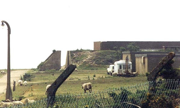
Viewed from first the south west and then the south east, the site appeared like this, and that was the state when the author was posted to Ventnor in 1957. In 1950 the CH system was refurbished, but during the ensuing decade the ROTOR system was installed and the remaining CH towers were dismantled in the summer of 1957, this
event being witnessed by the author. Some of the timber from the Receiver towers was used for the floor of the pipe store in the Council Yard in Upper Ventnor, for the reconstruction of a bridge
over a footpath at Wheelers Bay, for timbering sewer trenches and the reinstatement of groynes.
T Block, which is shown here behind the Type 80 building was removed in the sixties decade. In October 1962 the R Block area was purchased by the GPO who retained it until 2005 when BT sold it together with a tall slim mast to an undisclosed buyer for the sum
of £61,000. Since then the new owner removed the few remaining artefacts and perforated the foot thick walls with many rectangular holes. Also the four feet deep gravel bomb trap has been removed
from the roof. After which, seemingly it has been abandoned and word has it that the local youth now use R Block for "raves".
If you have been interested enough to read down to here then the Bawdsey Website is certain to be of interest.
And if you served at RAF Bawdsey at any time you should look at this Old Friends contact site.
Also there are two anecdotal sites about the the West Coast CH as installed in the
Isle of Man.and
Scarlett Point
FOOTNOTE : "Radar Reflections" by Michael Cumming (ISBN 1-894255-10-0) tells how 500 Technical Officers and 5000 radar mechanics were recruited and trained in Canada. James
Rowlatt was undoubtedly one of these. His signature appears on this 1942 Christmas Dinner menu.
CH radar is recorded in stained glass at Goodrich Castle.
Text © 2007 D.C.Adams Rev 03.10.19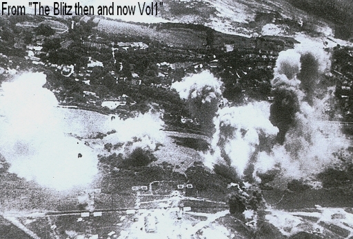
 appeared as moving patterns over the tube face.
However a blue filter over the long persistence tube permitted only the relatively stationary echoes to be seen. When the Germans eventually used 'window', masses of faint returns covered the tube. It was
found that if the tube brightness was turned up fully and then sharply down, for a short period the window returns were no longer visible but the stronger signals from aircraft were. This technique then
had to be repeated continuously.
appeared as moving patterns over the tube face.
However a blue filter over the long persistence tube permitted only the relatively stationary echoes to be seen. When the Germans eventually used 'window', masses of faint returns covered the tube. It was
found that if the tube brightness was turned up fully and then sharply down, for a short period the window returns were no longer visible but the stronger signals from aircraft were. This technique then
had to be repeated continuously.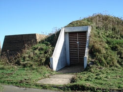 The transmitter and the receiving equipment for this device were housed in a bunker (shown to the left) within the legs of the tower. VEB must have been a great boon to RAF Ventnor as
they were at last able to find their own heights. However VEB had but a relatively short life as it was replaced in 1944 when the 'nodding' centimetric height finders which could look to any point of the
compass became the standard.
The transmitter and the receiving equipment for this device were housed in a bunker (shown to the left) within the legs of the tower. VEB must have been a great boon to RAF Ventnor as
they were at last able to find their own heights. However VEB had but a relatively short life as it was replaced in 1944 when the 'nodding' centimetric height finders which could look to any point of the
compass became the standard.
In
November 1947 one of the wooden receiver towers had to be dismantled after being severely damaged when an Avro Anson Channel Isles mail plane from Croydon, flying off course in very poor
visibility, crashed into it. Peter Snowdon (Sourced from: http://ventnorblog.com/2007/06/04/life-at-the-ventnor-radar-station/#ixzz1cFp0Y28e ) has this to add :- "The aircraft crash you are referring to
was an Avro Anson G-AIWW flown by my father George Snowden with navigator Corrie on 20th Nov.1947 which was the Queens wedding day to Prince Phillip.
They were in thick fog trying to land at Ventnor airport (sic). My father who had been a Battle of Britain Hurricane pilot with 213 Squadron, scored 5 1/2 confirmed and 2 damaged and 2 probables and
was shot down twice himself, force landing on each occasion." ( Author's note: There was no Ventnor Airport as such, but other airfields existed on the Island.)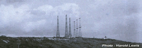
 Click on this thumbnail to reach Boffinstv which is a website offering an hour
long professionally produced DVD of BBC quality about the early days of RDF (although it is referred to as radar throughout.) It is the familiar story from the German build up through to the Blitz
with emphasis on the importance of the CH chain, the principal point being that the pre-war Graf Zeppelin scientific survey failed Hitler very badly. There is a good balance of archive and dramatic
reconstruction clips interleaved with new material in the form of verbal statements from our early radar scientists. Background music is kept to a non intrusive level and the suitably grave tones
of the commentary are always clearly audible. For this viewer a rather more technical content would have been pleasing, so in that one aspect alone I would submit that what I have provided above
is more informative. However, for possibly the first time in this form of media, CH is given its true most worthy place in history and not just mentioned in passing. On the whole the DVD is a good
buy and I certainly do not regret the outlay.
Click on this thumbnail to reach Boffinstv which is a website offering an hour
long professionally produced DVD of BBC quality about the early days of RDF (although it is referred to as radar throughout.) It is the familiar story from the German build up through to the Blitz
with emphasis on the importance of the CH chain, the principal point being that the pre-war Graf Zeppelin scientific survey failed Hitler very badly. There is a good balance of archive and dramatic
reconstruction clips interleaved with new material in the form of verbal statements from our early radar scientists. Background music is kept to a non intrusive level and the suitably grave tones
of the commentary are always clearly audible. For this viewer a rather more technical content would have been pleasing, so in that one aspect alone I would submit that what I have provided above
is more informative. However, for possibly the first time in this form of media, CH is given its true most worthy place in history and not just mentioned in passing. On the whole the DVD is a good
buy and I certainly do not regret the outlay.
When describing military units it is conventional, courteous and appropriate to cite the names of the Commanding Officers, but until now (March 2007) the author had no knowledge of any of those
at Ventnor during the CH days. Now he is pleased to report that in 1942 Fl/Lt James Rowlatt RCAF served in that capacity and also as Technical Officer. Previously at Trevose Head, he later served
similarly at Pevensey, Swingate, and St. Margaret's Bay. Amazingly Fl/Lt Rowlatt was still alive and well in 2007 aged 102 living in the land of his birth. We salute you Sir! During his time at Ventnor
he increased the air defences with Lewis and other guns as frequent opportunistic attempts to attack the site at low level were made by the enemy. Thanks to his son Les for providing this information,
and it is hoped to hear more.