

|
|
|
|
The Decca Type 80 was designed in the nineteen fifties by a team at Decca headed by Ron Burr for use as either Ground Controlled Interception purposes or for Early Warning Search. It was to replace the aged Chain Home equipment and represented a huge leap forward in technology. Many CH stations were closed down soon after the war and there was a lull in R & D for economy reasons. However the Berlin Airlift in 1948 and the Korean war in 1950, both of which suggested world-wide Communist ambitions, prompted more urgent efforts. Thus at the Radar Research Establishment (RRE) an embryo Type 80 was derived from an experimental set up encoded as Green Garlic. This was made up from two Type 14 reflectors bolted end to end on Type 7 turning gear which also carried the transmitter, the modulator being on the ground. With a 1.5 MW magnetron and improved receiver the performance obtained was an enormous improvememt over any existing equipment.
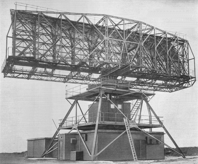
With CH, an error in reported target bearing was quite normal as the fixed dipole aerial system had a basic acceptance angle of about 60 degrees, which the goniometer in effect reduced to a plus or minus five degrees error. However the Type 80 could distinguish two aircraft a mile apart at 150 miles and had a stated reliable range of 200 miles although considerably greater was usually seen. This was achieved by using a huge aerial reflector measuring no less than 75 feet wide by 25 feet high, this being fed from a magnetron delivering massive 2 megawatt pulses of 2 (or 5) microsecond duration at a Pulse Repetition Frequency (PRF) of 270 per second. The aerial's narrow acceptance angle of a third of one degree meant that it had to turn at a slow rate to achieve good 'illumination' of the distant target and yet not have rotated too far on to miss receiving the reradiated returned signals. This massive structure was turned by two or sometimes four 50 HP motors.
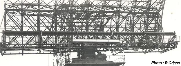
Front view showing the'leaky waveguide' in the dark coloured perspex tube positioned across the width of and at the focus of the reflector, with the much smaller IFF aerial mounted beneath.
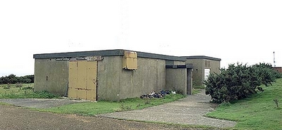
The power consumption of this huge beast totalled 160 kVA and interesting techniques were used to provide and control this energy. The 'annex' to the main building (i.e. the part of the building outside the
legs in the picture above) contained a large motor alternator set equipped with a very heavy flywheel. The motor was fed from the Electricity Company's 3 phase supply and the flywheel buffered the
radar's turning motors varying demand as the reflector turned through the wind.
This excellent picture kindly supplied by an ex radar fitter, who served some twenty five years later than me. (If you arrived here from 'End Game' Click to return to your place there)
To supply the modulator, the lower annex contained the induction regulator and the 12 phase transformer.
The former was built like a large induction motor and was fed from the 3 phase supply. However, it did not spin but behaved like a variable transformer, the rotor being normally clamped stationary but
allowed to move slowly round over about 270 degrees by a push-button controlled motor allowing the modulator and eventually the magnetron, to receive a gradually increasing voltage during
the 'running up' process. The regulator's three phases fed a transformer which provided 12 output phases and these were taken to twelve anodes within a large mercury arc rectifier known as 'The Mekon'.
This was a very dramatic blue glowing and hissing device housed at chest height in a cabinet in the main room and its rectified output provided a reasonably smooth 600vdc diet for the modulator. This
is what it looked like:-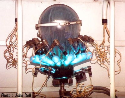
The modulator was contained within the largest cabinet in the room. The front had a glass window and within could be seen the Pulse Forming Network, a 25:1 ratio transformer, a mercury pool switch and porcelain insulators everywhere, and the combined effect of these components was to brew up the enormous 25kV pulses to send up to the magnetron. That was situated in the rotating cabin so a bank of sliprings were mounted on an axial column which came down from the cabin and rotated with it. The 25kV pulses were applied to the end of a highly insulated conductor which went co-axially up the centre of the column.
Also downstairs was the 'Emotrol' turning motor control cabinet. Details of the turning gear are provided on a separate page.
One corner of the room was partitioned off to form a small office and this was equipped with just a bench, chair, and table. The literature consisted of Air Publications, a Signal Office Diary 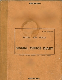 and the Meter Readings Book. There were about fifty meters built into the various cabinets, giving some indication of the state of health of the electronics the cabinets contained and their readings were required to be recorded every two hours. All the units had associated cooling fans and when one was 'on watch' their combined noise was difficult to live with. It was always a relief to get out into the fresh air.
Outside a metal staircase led to the gantry in the centre of which rotated the cabin. This was about 15 feet square and to gain entry one had to leap aboard the thoughtfully provided running board and then slide back the door. Walking across the floor during rotation was a strange experience somewhat reminiscent of inebriation. One side of the cabin was occupied with cabinets containing the transmitter, TR switch, receivers and test equipment. Another corner housed an air pump cabinet. The transmitting device was a water-cooled magnetron which on receipt of the high voltage pulse from the modulator immediately generated the 2 megawatt (for Type 80 Mk.3, the earlier Mk.1 had a 1 Megawatt magnetron) burst of radio frequency energy in the 3000MHz band and immediately stopped doing so when the modulation pulse ceased. The RF pulse was ducted through the top of the cabin by means of a rectangular waveguide eventually becoming equally distributed at the focus of, and along the length of the reflector using the 'leaky waveguide' method. That is, via angled narrow slots cut into the smaller dimension of the waveguide. This part was enclosed in a perspex tube as the waveguide was pressurised by an air pump which reduced any tendency towards arcing.
 The TR switch was an extremely cunning arrangement of circles and short bits of waveguide known as 'the rat race'. This allowed both transmitter and receivers to use the common aerial array without the receiver being blown to pieces by the massive transmitter pulse. I rate this as the most electronically elegant piece of engineering in the whole of the Type 80.
In this diagram the output pulses from the magnetron arrive at the top left and leave for the aerial top right.
The very low amplitude received signals were fed to two receivers after being mixed with the output from the local oscillator klystron which differed in frequency from the magnetron by 13.5 MHz. The resulting received signals were then carried by this resulting intermediate frequency. In the diagram the klystron is shown bottom right and the IF output for the receivers departs to the right from the centre ring.
However, magnetrons have a tendency to drift in frequency so Automatic Frequency Control corrected the local oscillator frequency as necessary to cause an IF always of 13.5MHz. One receiver amplified the signals in a linear way, the other in a logarithmic manner. The signals were then carried to the underground installation via co-axial cables and distributed to the consoles. The radar operator could choose the output of either receiver, and the linear one was the normal choice. Logarithmic was used if the target returns were obscured by thunder clouds when as if by magic the dense patches on the display thinned and allowed the pinhead sized echoes to be seen. It was expected that this receiver would also have been effective against certain forms of jamming too. The Type 80 system proved to be so sensitive that it unexpectedly was found to be even capable of detecting flocks of birds, this mystifying transient "interference", when observed being described as "angels".
Outside, back on the gantry, stairs led to the upper platform where the bottom of the reflector circled barely a foot above one's head and here were located the two turning motors.
Later other large radars were developed which had a family resemblence to the Type 80, but in short the only common components were the framework, the rotating cabin and the turning gear. The reflectors and electronics of those radars were of necessity more complex to achieve the results required in the age of ballistic missiles. The author has no personal knowledge of those developments so has not attempted to describe them.
 The first operational Type 80 was at Trimingham in 1954 and the one at Ventnor entered service on the twentieth of March 1956. It had but a short life there, being carefully dismantled during the summer of 1959 and removed in sections on Decca specifically adapted low loader lorries, possibly to be resurrected elsewhere. But many other Type 80 sites were also being closed down around that time as the current threat then was perceived to be less from the Bison bomber and more from the H bomb delivered by ICBM, and the main defence policy against that was 'deterrence'. The Fylingdale BMEWS presumably served mainly to provide the US with a short warning. In addition, due to the proven reliability, where Type 80 cover overlapped some installations were deemed no longer neccessary. Hence Ventnor closed but Sopley remained.
When the entire Ventnor site was transferred in March 1962 to the Ministry of Aviation for sole civil use, the Modulator room remained but was no longer needed. However it survived for many years, not being demolished until some time after 2009. However one Type 80 outlived all the others, the one at RAF Buchan providing useful service until 1992, having operated continuously for 37 years. The closing down ceremony was attended by two of the orignal Decca Type 80 production engineers..
About 35 Type 80s were built and some were installed in overseas locations. The RAF operated one at Troodos in Cyprus and Nato had one at Metz in France, operated by Canadians. A Swedish site visitor has informed me that besides "those in Germany" there were four in Sweden. The first of these became operational in 1957 and the fourth in 1963. Code named as Tom, Dick, Harry --- and Fred, they continued in service until 1978/9. Could Fred have been one of the redundant UK machines reborn?The list of sites on the right was obtained from my copy of the limited edition book "The Decca Legacy" by R.L.Burr who was the Chief Engineer at Decca and is shown here with the general permission granted in the book. Strangely, for whatever reason, eleven sites have been omitted from this list. In Germany they were erected at RAF Brockzetel, Breckendorf, Uedem and Auenhausen , all being originally operated by the RAF before being handed over to the Germans. Then there were those at RAF Madalena in Malta, Christmas Island, Faraid Head (which was at Cape Wrath), Beachy Head, Bempton, St.Margarets Bay and ........ yes you've guessed it, AT VENTNOR!
I have been contacted by Alan Stiles who worked for Decca and helped in the construction of the very earliest Type 80s and was present at Bard Hill in Norfolk when the prototype machine rotated for the first time.
Return to Locking Page 7
Rev 150516