

|
|
|
|
The Marconi Type 13 height finder was introduced in 1942 and remained (with improvements) in service until well into the nineteen seventies. The 'nodding horror' as it was sometimes called was developed from the Naval Type 271 and used the high power cavity magnetron. This compact device worked in the 3000MHz band and could churn out 500kW, allowing targets at 25000 feet to be detected at a range of about 150 miles.
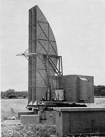
The picture on the right is of the original version with a 'cheese' aerial with parallel reflectors, one for transmission and the other for receiving. Later versions were fitted with the newly invented automatic Transmit / Receive switch which allowed a single reflector and that was made of aluminium rods. But before describing the Type 13 in detail, a more general description of this system of radar is required, as it is very different from the CH method. We have now advanced to the type of radar display that is familiar to most: the Plan Position Indicator (PPI). The CRT now has a trace that is a moving radial line, the origin of which is the centre of the face of the tube. A target is shown as a small 'sausage' at a right-angle to the line. The display is fed from a steadily rotating 'search' radar which may be the Type 13's brother, the Type 14, which is an almost identical machine, but has a fixed aerial (25 X 8 feet) mounted horizontally. The operator is immediately able to read off the bearing of the target from a scale of degrees mounted in a ring around the periphery of the tube. The range being the distance from the origin along the trace to the target. The operator is aided in this measurement by 'range rings' which are a superimposed display of bright concentric circles produced electronically at known mileages apart and available at the touch of a switch.
Let us consider briefly how a human might ascertain the location of an aircraft in his vicinity. First he would rotate his head to what he thought was the right direction: then he would scan up and down until he spotted it. And that is how the Type 13 worked. A dedicated display (the Heights Console) adjacent to the PPI already described had a trace which originated from near the southwest periphery and rocked over an arc in time with the Type 13's nodding reflector. The operator of the PPI could switch on a 'strobe mark' which was a bright radial line about a centimetre long, the position of which was controlled by two knobs. One moved the strobe mark along any radius chosen by the other knob which moved the strobe to any chosen angular position. Thus the PPI operator was able to cause the strobe to bisect any target on his display in which he was particularly interested, probably needing to make small final jiggles of the knob to get the strobe exactly in the middle of the echo. This second knob was spring loaded to a central zero position, so that in use a large left or right movement made the strobe mark accelerate quickly and small movements close to the central zero point enabled the final positioning. While this was being done, up in the fresh air, also obediently following those movements was the two ton cabin of the Type 13, accelerating fiercely and slewing to its new position and jiggling a little whilst nodding unceasingly. The trace on the Heights Console moved in synchronism with the nodding aerial and targets appeared as small bright arcs somewhere along it. The face of the CRT was marked in miles horizontally along the lower edge and at points further up the surface, horizontal lines which corresponded to heights had been drawn in ink by hand, the result of lengthy calibration flights by a suitable target aircraft. In later years this was always a Canberra medium bomber, the broad wing of which provided a strong return. Hence, with the Type 13 pointed at the target selected on the PPI display, any echo at any indicated height on the Type 13 console would be from that target.
So how did the turning of a knob cause a two ton steel box to perform those antics? It was done by courtesy of the Pivot Mount servo-controlled turning gear. Turning Gears were studied as a separate part of the course at Locking as there were various types of which Pivot-Mount was the most complex. On the original rotatable radars, turning was achieved by man power! Employment of a simple electric motor would have been an improvement, but it would have tended to slow down when the aerial crossed any significant wind, and the cabins certainly could not have been able to jump from rest to a new bearing as just described. As the name suggests, pivot-mount required a strong post around which the cabin rotated. The post rose out of the thick concrete roof of a ten foot high brick built one room building, known as 'the plinth'. The post had a toothed ring, and over this was dropped the gearbox of the turning mechanism. The gearbox had an integral 5 horsepower DC motor and 250:1 reduction gearing engaging with the toothed pivot. A shaped hole in the floor of the cabin allowed it to be lowered over the pivot mount mechanism and bolted to a flange below the gearbox. Hence externally there was no indication of how the cabin was mounted - all one saw was a big box sitting on top of the plinth. At Locking there were three of these weird looking units (sans cabin) and their associated control electronics in the classroom and we had great fun driving them.
The heart of the control system was an ingenious electro-mechanical amplifier known as an 'amplidyne'. This lived in the plinth and consisted of a six horsepower three-phase constant speed induction motor, driving a DC generator. In simple terms the output from this was almost short circuited. The resulting large currents caused enormous magnetic fields to cut across the true output coils. This output was connected to the armature of the turning motor. Currents up to eighty amps could flow, the turning motor having a fixed DC supply to its field winding. The field winding for the amplidyne DC generator was supplied from the output valves of an electronic amplifier, with there being no output from this if there was no input. Now guess where the input came from. Yes you are right: from that knob being so carelessly twiddled by the radar operator of course, the poor old two ton Type 13 nearly jumping off it's pivot while faithfully emulating the twiddles with the amplidyne screaming in protest! Yes, it truly did, as a characteristic of the amplidyne was that it voiced its audible distress if so abused - it literally screamed at each change of aerial direction. Negative feedback was provided in abundance (100 volts) to subdue jerkiness, and this compensated for windage in a steadily turning Type 14 because a reduction in r.p.m. of one sixteenth resulted in a reduction of feedback of one volt. As the input (from the knob in the case of the Type 13) to the amplifier needed to be only one volt to turn the aerial at full speed, the nett effect of doubling this input, was for the turning motor to receive a vast boost to bring the speed back up again.
An interesting point is that due to their Naval parentage, all the AC supplies to the Types 13/14 were at 180 volts and 500Hz frequency as this was the Naval standard. The higher frequency allowed less iron to be used in the motors and transformers, which gave a significant saving in weight.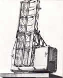
The cabin was a steel box 12'6" wide by about 6 feet deep and 6 feet high. On the front top edge were mountings for the reflector pivots and on the top of the cabin was the 'nodding'motor and gearbox from which emerged a reciprocating arm attached to the reflector some distance above the pivots. The reflector nodded at a fixed rate of six per second. Along the bottom rear edge of the cabin there was an 18 inch running board allowing access to either of the left or right-hand doors. On entering one immediately noticed the top of the pivot mount because a tall cylinder which housed the slip-rings, an extension of the pivot, almost reached the roof. A hand crank protruded from the turning gear but this could only be engaged after operation of an interlock plate, this switching off power to the turning motor.
So how did this machine transmit and receive? Well, a modulator was required to generate the high voltage narrow pulses to drive the magnetron. The modulator box contained two thyratrons valves, one large, one small. These blue glowing gas filled switches together with a pulse-forming network and the overswing diode did their job 270 times a second at the receipt of each master timing pulse from the underground 'Radar Office'. Also mounted in the modulator box was the variac. This variable transformer controlled by a large round handle allowed the output voltage of the modulator to be gradually increased to maximum during the 'running up' procedure. Standing on top of the modulator was a indicator unit fitted with a six inch CRT. On the horizontal trace of this could be displayed the output of the receiver, a target showing as an upward spike.
In the right-hand corner stood the transmitter cabinet containing the magnetron with its immensely powerful horseshoe magnet. When changing magnetrons one had to insert a cylindrical keeper into the jaws of the magnet. The efforts of two men were needed to remove it. Waveguide led from the 'maggie' through the side of the cabin where it turned upwards. The next section of waveguide was constructed in the form of a long rectangular brass spring coated in rubbery pitch material. This flexible waveguide allowed for the angular nodding of the reflector. The wave guide continued to the pivotal area of the reflector, which was about 25 feet long by 6 feet wide, built from duraluminiun tubing. The waveguide continued to the lower end of the reflector where it then turned and ran back up within a perspex tube at the focus of the curved reflector. The narrow edge had machined slots in alternate directions, and these distributed the RF energy equally at all points along the aerial. Back at the magnetron, a horizontal section of waveguide had an aperture in the narrow edge. Into this could be lowered by means of a screw mechanism, a row of ten very miniature fluorescent tubes. The RF energy caused these to illuminate and because of the 'standing wave' within the waveguide the tubes lit at different levels. The heights of maximum and minimum levels read against an etched scale could reveal the output power being produced and other diagnostic information.
The receiver stood on top of the transmitter and occupied very little space, merely consisting of a klystron oscillating at 45MHz above the magnetron frequency ( 3000 MHz, 10cm wavelength), an IF amplifier strip of about six valves and some short bits of waveguide forming a Transmit/Receive switch which allowed the receiver to be only connected to the common aerial waveguide when the transmitter was not sending its pulse. Perhaps that should have been put the other way round: a radar transmitter spends the vast majority of its life doing nothing at all. During every second, at a PRF of 250 pulses per second, only about one millisecond is spent in transmitting, allowing 999 milliseconds for receiving. The klystron in those days was only a low power device but very useful as a local oscillator as its frequency was extremely stable but could be altered by varying the anode voltage. The mixer consisted of a diode inserted into the waveguide, the klystron which oscillated at 45 MHz above the magnetron feeding one end of it and the difference frequency of 45MHz appeared at the other. Because magnetrons tend to drift in frequency to some degree, automatic frequency control had to be applied to the receiver i.e. make its tuning change to follow any magnetron variation, so as to always produce the 45MHz IF, this being done by automatic alteration of the klystron anode voltage. A frequency comparator very similar to those found in the much later FM radios was the basis of generating this control voltage.
Daily Routine Maintenance at Ventnor was a simple affair. First one had to ensure that the cabin could not suddenly turn whilst clambering on to the running board from the vertical iron plinth ladder, by operation of a safety switch in the plinth. Then up in the cabin the first task was to check the Standing Wave Ratio and power output. Next the cabin had to be hand-cranked round to the bearing for Cherbourg and the AFC switched off. The Peninsula head was some 65 miles distant, but its echo was so large that it could always be seen on the monitor display even if the receiver was well off-tune. Next, fine adjustment of a tuning plug on the klystron was required to maximise the tiny echo being received from the small radar reflector on top of the Cherbourg lighthouse, following which the AFC was switched back on.
Larger pictures & Simulation...or...Take leave...
Return to RAF Locking Page 4 or Page 6 as required.
Text © 2006 D.C.Adams
Rev140614