Having completed the theory part of our training we were now qualified to
begin the technical part, and this was to start with a three week session about
something called 'Turning Gear'. We had said farewell to our previous academic
theory instructor and now we had a grizzled sergeant to instil the practical
application of all those theories. Well, yes we all knew that radar aerials
usually spent their lives merrily spinning around, but why should anything more
than a suitably strong electric motor be needed to achieve that? We were about
to find out.
We were told that in a few weeks we would be learning about a radar known as
Type 7. It seemed that it had a pretty hefty aerial shaped somewhat like a giant
bed frame. Fifty four feet long by thirty feet high in fact, and its near twenty
tons mass needed to rotate steadily at usually 4, but up to 6 rpm. This steady
speed was necessary as the radar operators reckoned to determine a target's
speed by the distance the echo on their display advanced in successive
revolutions of the trace (i.e. the aerial). The problem was that any ordinary
electric motor would not be able to keep the speed of a bulk of that size
anywhere near constant in any worthwhile breeze. A means of boosting the speed as
the aerial slab faced the wind and a means of reducing the drive as the aerial
became in line with the wind was required, and it had to be done completely
automatically. Such a system is known as a 'servo system' and these always rely
on something called 'negative feedback', whereby a tendency to slow is detected
and a boost given to reduce the tendency, and vice-versa. Fortunately the need
for such precise automatic control of a powerful electric motor had already been solved in
civilian engineering, for example in coal mine winding gear, and the system was
called 'Ward-Leonard' in honour of it's inventors. To avoid boredom,
non-technical readers may choose to skip the next paragraph.
Out at the aerial a fifteen hp DC motor (the Aerial Turning Motor or ATM), mounted in the base, drove
the aerial round via a worm then a chain reduction drive. Back in the plant room was a twenty four hp 'constant speed' AC
three phase mains driven motor. On the same shaft there was a thirteen kw DC
generator and a two kilowatt DC 'exciter' generator. The output of the exciter
generator provided the supply for the fields of the remote ATM, and in parallel,
but via the manual speed control potentiometer, the field coils of the 13 kw
generator. The exciter's own field was also in parallel with these but via an
electro mechanical 'Isenthal' regulator. The DC armature output of the 13kw
generator was connected directly to the armature inputs of the ATM. When windage
caused the aerial to slow, the additional load was felt by the 13 kw generator
and therefore also by the AC driving motor it, which of course tended to slow, and most
importantly, the exciter generator did too as it was on the the same shaft. If the
exciter slowed then the DC it was generating was reduced. However, reduced field
current in any DC motor, by a miracle of electrical science, makes that motor
go faster or if it is a generator we are talking about as in this case, give greater output. Hence the ATM was given a boost and the tendency for the aerial to slow was reduced.
Any speeding up of the aerial due to
windage was similarly self correcting via the reduced loading reflected back to the
exciter. There was one Ward Leonard set for us to play with, but due to it's
size and cost no Type 7 aerial was provided to be rotated by it.
With Ward Leonard barely assimilated we were introduced to the
'BTH Type 21' turning gear. This was a more lightweight but more versatile
equipment. However we would be unlucky to come across one of these it seemed, but if we
did it would be in a stationary steel cabin at the top of a 200ft.steel tower
where it would be rotating a ten foot diameter parabolic dish aerial mounted on the roof of the cabin. Known as
Type 54, this device provided a pencil beam for the low looking Coastal Early Warning radar
which could rotate continuously in either direction, sweep backwards and
forwards over an operator selectable sector, or be turned to any particular
bearing and be held stationary there. It was a cousin of Ward Leonard but only needed a two hp
motor as it's basis and the ATM was only of 1.5 hp. It was mostly electro
mechanical in design, but some tricky sounding 'phase sensitive rectifiers'
electronics were involved. One week was all that was devoted to these two
turning gears.
 The next two weeks
were dedicated to 'Pivot Mount', another versatile set of machinery used
extensively to turn Types 13 and 14. I shall not go into it's intricacies here,
as I believe that those are sufficiently well covered already in my RAF Ventnor pages, and it
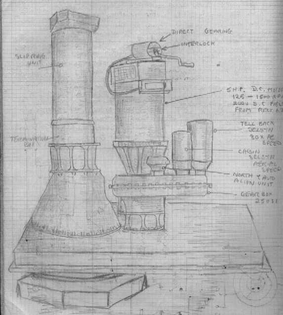
is enough to say that I found it highly interesting but brain taxingly complicated. It was my introduction to the way relays may be used to achieve all
sorts of logical control and the amazing 'Amplidyne', an electro mechanical
amplifier, was a revelation of man's ingenuity. This motor-generator type
machine literally screamed an audible protest as it was forced to bear the
burden of jumping a two ton radar from one bearing to another. Three sets of
this equipment were provided for our amusement and on the right I provide a very
poor artist's impression of one of them. When driven, the offset mass of the
gearbox and the flat cabin mounting platform, rotate around the 'pivot' which is
enclosed in the lower part of the structure on the left. In use the hexagonal
base of the 'pivot' is mounted on the concrete roof of the 'plinth' building.
The cabin is designed to fit over the rectangular part resulting in the 'pivot' being central within it.
The next two weeks
were dedicated to 'Pivot Mount', another versatile set of machinery used
extensively to turn Types 13 and 14. I shall not go into it's intricacies here,
as I believe that those are sufficiently well covered already in my RAF Ventnor pages, and it
is enough to say that I found it highly interesting but brain taxingly complicated. It was my introduction to the way relays may be used to achieve all
sorts of logical control and the amazing 'Amplidyne', an electro mechanical
amplifier, was a revelation of man's ingenuity. This motor-generator type
machine literally screamed an audible protest as it was forced to bear the
burden of jumping a two ton radar from one bearing to another. Three sets of
this equipment were provided for our amusement and on the right I provide a very
poor artist's impression of one of them. When driven, the offset mass of the
gearbox and the flat cabin mounting platform, rotate around the 'pivot' which is
enclosed in the lower part of the structure on the left. In use the hexagonal
base of the 'pivot' is mounted on the concrete roof of the 'plinth' building.
The cabin is designed to fit over the rectangular part resulting in the 'pivot' being central within it.
At
the end of the two weeks, besides having to endure the 'question and answers'
test paper, we were 'boarded' on the Turning Gears. This involved three grizzled
Flight Sergeants quizzing us individually on the technical drawings and theory
of operation, and it lasted for about an hour if one did not make too many
mistakes. A typical question was 'Show me how Sector Sweep works'. The student
had to pick the correct starting point on the several large circuit and relay
diagrams and follow the correct paths to achieve sector sweeping. If he took a
wrong path the examiner did not bother to point it out: he waited until the
unfortunate student discovered that for himself. A few small mistakes seemed to
be acceptable provided the examinee realised his error fairly quickly. I shall
always remember that my examiner was so competent that he was able at the same
time to practise Morse communication with a colleague, using a key under the
table on his knee and wearing a single ear-piece, while still following my
hesitant explanations like a hawk. It was a nerve wracking day for all of us,
but amazingly we all passed this most severe form of testing. We were ecstatic,
another milestone passed and we were still all together. The following week we
were to start on the last stage of our training by learning about the Radar
equipment itself.